Pneumatic spool valves at best price in india Valves, which control the direction of the flow of the compressed air How to read a spool valve schematic drawing
Pin en Woodworking tools
Types of pneumatic valves Valve air way port four works five Hydraulic spool valve diagram
Valve solenoid pneumatic way position working principle work does valves circuit two normally closed open cut gas 220v 12v turned
Pneumatic directional control valve symbolsHow pneumatic valves work? types of valves in pneumatics Vevor hydraulic valve 2 spool hydraulic joystick control valve 11gpm[diagram] 3 position valve diagram.
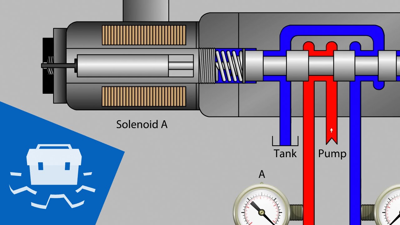
Simplified scheme of the pneumatic valve [4].5 2 solenoid valve circuit diagram Spool zhuSolenoid valve actuator symbol solenoid valve symbols.

Tilt valve spool
Solenoid valve symbols explained solenoid valves descriptivePin en woodworking tools 5/2 plastic 1/8" pneumatic spool valve with roller lever[diagram] 3 way pneumatic valve diagram.
Valve spool pneumatic valves presentationPneumatic valves: diagram, types, working & applications [pdf] Pneumatic schematicPneumatic valve valves principle eltra spool ports pneumatics types.

Pneumatic high pressure spool valve with anti drip suck-back feature
Entendendo a simbologia das válvulas direcionais pneumáticasHow to read a spool valve schematic drawing Spool valve diagram valves pneumatic control air direction controlled graphic internal zaworu flow dryers pneumatics indirectly auxiliary supply channelSpool pneumatic valves.
Pneumatic symbols circuit valve explained position lever spring return actuated symbol flow figure checkValve spool tm tilt bucket Design and calculation of the technological process for the part spoolPneumatic automation explained by the valveman valve store.

Spool valves: how they work and how to read their symbols
Design and calculation of the technological process for the part spoolMachine drawing: rotary four way valves Spool valve valves poppet pneumatic types stainless sleeve match ground instrumentationtools actuation consumption watts low powerHow five port four way air air valve works.
Pneumatic actuator principle pinion rack actuationPneumatic circuit symbols explained |library.automationdirect Structure of pneumatic control valveValve spool acting joystick loaders tractors vevor 150psi.

Pneumatic simplified
What is a spool valve?Schematic showing the contact between a valve spool and a valve body How does 3/2 way pneumatic solenoid valve work?Way valves two valve spool control three flow four direction ports pressure rotary drawing port hydraulics machine other part.
.

![Simplified scheme of the pneumatic valve [4]. | Download Scientific Diagram](https://i2.wp.com/www.researchgate.net/profile/Yan-Fu_Li/publication/269405807/figure/download/fig3/AS:614015780794381@1523404178422/Simplified-scheme-of-the-pneumatic-valve-4.png)
Simplified scheme of the pneumatic valve [4]. | Download Scientific Diagram

solenoid valve actuator symbol Solenoid valve symbols
5 2 Solenoid Valve Circuit Diagram

how to read a spool valve schematic drawing - Wiring Work
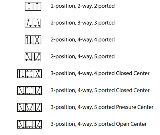
Pneumatic Directional Control Valve Symbols

solenoid valve symbols explained Solenoid valves descriptive

5/2 plastic 1/8" pneumatic spool valve with roller lever - Senga